Networking-Blog

My WordPress Blog

Intro to VRF lite


VRFs, or VPN Routing and Forwarding instances, are most commonly associated with MPLS
service providers. In such networks, MPLS encapsulation is used to isolate individual customers’
traffic and an independent routing table (VRF) is maintained for each customer. Most often, MP-BGP
is employed to facilitate complex redistribution schemes to import and export routes to and from VRFs to
provide Internet connectivity.

However, VRF configuration isn’t at all dependent on MPLS (the two components just work well together).
In Cisco terminology, deployment of VRFs without MPLS is known as VRF lite, and this article discusses a
scenario where such a solution could come in handy.

Assume the topology illustrated below is a network owned by an enterprise. As you would expect, normal
company traffic must pass through the firewall so that company policy can be enforced. However, this a
secondary Internet connection has been added to this network: an unrestricted ADSL circuit designated for
guests visiting the company campus.

The 10.0.0.0/16 network is used for trusted traffic
The 192.168.0.0/16 is used for guest traffic.

All router interfaces which provide transport for both types of traffic have been configured with
two subinterfaces performing 802.1Q encapsulation; .

10 for VLAN 10 (blue)
20 for VLAN 20 (red).

Note that although 802.1Q encapsulation is used to tag frames across the link, each link is a
routed segment
with an IP interface at either end. For example, here is R1’s F2/0 configuration


R1

interface FastEthernet2/0
description R1
no ip address
!
interface FastEthernet2/0.10
encapsulation dot1Q 10
description VRF_BLUE
ip address 10.0.12.1 255.255.255.252

!
interface FastEthernet2/0.20
encapsulation dot1Q 20
description VRF_RED
ip address 192.168.12.1 255.255.255.252
!

We employ VRFs here to segment the single physical infrastructure into two virtual, isolated networks.
VRFs employ essentially the same concept as VLANs and trunking, but at layer three. 

VRF lite is simple: each routed interface (whether physical or virtual) belongs to exactly one VRF.
Unless import/export maps have been applied, routes (and therefore packets) cannot move from one
VRF to another, much like the way VLANs work at layer two.

Packets entering VRF A can only follow routes in routing table A, as we’ll see shortly.

To begin, let’s create VRFs BLUE and RED on R1:

R1(config)# ip vrf BLUE
R1(config-vrf)# description Trusted Traffic
R1(config-vrf)# ip vrf RED
R1(config-vrf)# description Guest Traffic

!

Next, we’ll add interface F1/0 (which connects to the guest-use ADSL uplink) to VRF RED:

R1(config)# int f1/0
R1(config-if)# ip vrf forwarding RED
!

% Interface FastEthernet1/0 IP address 192.168.0.2 removed due to enabling VRF RED
Wait a tick, what just happened?

When assigning an interface to a VRF, IOS automatically deletes any preconfigured IP address
to remove that route from the global table. Now when an IP address is assigned to this interface,
its network gets added to the specific routing table for that VRF.

So, we reapply our IP to F1/0.

R1(config-if)# ip add 192.168.0.2 255.255.255.252


 Current configuration of F1/0
!
interface FastEthernet1/0
description RX
ip vrf forwarding RED
ip address 192.168.0.2 255.255.255.252
!
The 192.168.0.0/30 route is gone from the global table; it now resides in the VRF RED table,
which we have to inspect separately by appending the vrf argument to show ip route:

R1# show ip route vrf RED

[…]

192.168.0.0/30 is subnetted, 1 subnets
C 192.168.0.0 is directly connected, FastEthernet1/0

 As you can imagine, this extra step of reapplying an IP address must be repeated for every interface
we add to a VRF.

Relevant finished configuration of R1:

interface FastEthernet1/0
description RX
ip vrf forwarding RED
ip address 192.168.0.2 255.255.255.252
!
interface FastEthernet1/1
description FW
ip vrf forwarding BLUE
ip address 10.0.0.2 255.255.255.252
!
!

!
interface FastEthernet2/0
description R2
no ip address
!
interface FastEthernet2/0.10
encapsulation dot1Q 10
ip vrf forwarding BLUE
ip address 10.0.12.1 255.255.255.252
!
interface FastEthernet2/0.20
encapsulation dot1Q 20
ip vrf forwarding RED
ip address 192.168.12.1 255.255.255.252
!
!
!
interface FastEthernet2/1
description R3
no ip address
!
interface FastEthernet2/1.10
encapsulation dot1Q 10
ip vrf forwarding BLUE
ip address 10.0.13.1 255.255.255.252
!
interface FastEthernet2/1.20
encapsulation dot1Q 20
ip vrf forwarding RED
ip address 192.168.13.1 255.255.255.252
!
As all interfaces now belong to isolated VRFs, our global routing table is completely empty.
We can verify that all 10.0.0.0/16 routes are stored in VRF BLUE, and all 192.168.0.0/16 routes
are stored in VRF RED:

show ip route vrf BLUE
show ip route vrf RED

At this point, although only R1 has been configured with VRFs, it can still route traffic to R2 and R3
with no problem. This is because, like VLANs, VRFs are only locally significant to the router.

##########################

R2 VRF Configuration :

ip vrf BLUE
description Trusted Traffic
!
ip vrf RED
description GUEST
!
!
interface FastEthernet0/0
no ip address
!

interface FastEthernet0/0.10
encapsulation dot1Q 10
ip vrf forwarding BLUE
ip address 10.0.12.2 255.255.255.252
!
interface FastEthernet0/0.20
encapsulation dot1Q 20
ip vrf forwarding RED
ip address 192.168.12.2 255.255.255.252
!
!
R3 VRF Configuration :

ip vrf BLUE
description Trusted Traffic
!
ip vrf RED
description GUEST
!
!

interface FastEthernet0/0
no ip address
!
interface FastEthernet0/0.10
encapsulation dot1Q 10
ip vrf forwarding BLUE
ip address 10.0.13.2 255.255.255.252
!
interface FastEthernet0/0.20
encapsulation dot1Q 20
ip vrf forwarding RED
ip address 192.168.13.2 255.255.255.252
!
!
##########################

Now configure our IGP. For this example, we’ll be running an OSPF instance per VRF.
We do this by appending the vrf argument to each router statement:

R1(config)# router ospf 1 vrf BLUE
R1(config-router)# router-id 0.0.1.1
R1(config-router)# network 10.0.0.0 0.0.255.255 area 0
!
R1(config-router)# router ospf 2 vrf RED
R1(config-router)# router-id 0.0.1.2
R1(config-router)# network 192.168.0.0 0.0.255.255 area 0
!
These are completely independent OSPF processes; as such, a unique router ID must be used for each.
(If you’re used to using IPv4 addresses as router ID, the IDs used above might seem strange.

Remember that the OSPF router ID is in fact an arbitrary 32-bit value simply expressed
in dotted-decimal.

Here, the third “octet” represents the router number and the fourth octet represents the VRF.)

After configuring the other two routers with two OSPF processes each,
we see two adjacencies formed per link, one per VRF:

R1 :


router ospf 1 vrf BLUE
router-id 0.0.2.1
log-adjacency-changes
network 10.0.0.0 0.0.255.255 area 0
!
router ospf 2 vrf RED
router-id 0.0.2.2
log-adjacency-changes
network 192.168.0.0 0.0.255.255 area 0

R3 :

router ospf 1 vrf BLUE
router-id 0.0.3.1
log-adjacency-changes
network 10.0.0.0 0.0.255.255 area 0
!
router ospf 2 vrf RED
router-id 0.0.3.2
log-adjacency-changes
network 192.168.0.0 0.0.255.255 area 0


Assuming our edge routers aren’t running OSPF, we’ll also create two static default routes
on R1, one for each VRF:

R1(config)# ip route vrf BLUE 0.0.0.0 0.0.0.0 10.0.0.1
R1(config)# ip route vrf RED 0.0.0.0 0.0.0.0 192.168.0.1


We can verify that our static routes exist along with their OSPF-learned companions in their
respective VRFs:

Finally we just need to advertise a default route in both OSPF processes from R1 so
R2 and R3 can learn them:

R1(config)# router ospf 1
R1(config-router)# default-information originate
!
R1(config-router)# router ospf 2
R1(config-router)# default-information originate

Note that when entering OSPF process configuration, we no longer need to append the
vrf keyword as it has already been applied.

Over to R2 we see that each VRF now has its own complete routing table:

show ip route vrf BLUE
O*E2 0.0.0.0/0 [110/1] via 10.0.12.1, 00:03:33, FastEthernet1/0.10

show ip route vrf RED
O*E2 0.0.0.0/0 [110/1] via 192.168.12.1, 00:01:41, FastEthernet1/0.20


VRF-Lite

VRF-Lite

The VRF is “Virtual Routing and Forwarding” to have multiple isolated IP routing tables
on a single device. When a route is added to your router all other connected networks will be
able to communicate with the new prefix unless you stop them by tools such as
access-control lists (ACLs).

There are some cases that you might like to have different instances of routing tables for different
purposes, such as simple example of guest internet access for guests, It’s an isolated network that
might pass some routers but should remain isolated. It’s something like
layer 3 VLAN, having two
or more isolated “routed” networks.
VRF lite is also termed multi-VRF CE, or
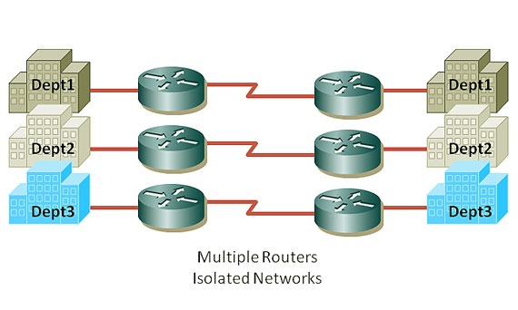
multi-VRF Customer Edge Device. Imagine two buildings with three networks connected to each
other using a WAN circuit, without VRF:

Without VRF

With VRF you can have isolation in a single device – separate routing table for individual interfaces:

VRF-Lite

While the “VRF Lite” equals to “VRF without  the need to run MPLS” in the network,
VRF plays a major role in MPLS networks. So whenever we use VRF without MPLS it’s VRF lite.
But why we need VRF in MPLS networks? Because we want to route customers networks,
they might have overlapped IP addresses. With having multiple VRFs, each customer can have the
same address that other customer might like to use without any problem :

VRF&MPLS

Interfaces in a VRF can be either physical, or logical, such as VLAN SVIs, but a Layer 3 interface
cannot belong to more than one VRF at any time. So the configuration should be easy!
First define each VRF and then allocate desired interface(s) to each VRF.

So let’s lab it up, Here’s our plan :

VRF Lite

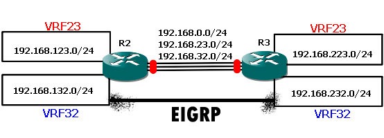
We have R2 and R3 connecting 6 networks together, three networks behind R2 and three
network on the right side of the above picture – connected to R3. One each router we create
two VRF, (and there’s always a global routing instance so total of three for each side).
One global routing table and two VRF – VRF23 and VRF32. We have same VRFs on R3.
The requirement is simple, making a connectivity between VRF23 on the right side to the VRF23
on the left side and so on for VRF32.

R2#show ip int br
Interface                  IP-Address      OK?
Ethernet0/0                192.168.0.2     YES
Ethernet0/1                192.168.23.2    YES
Ethernet0/2                192.168.32.2    YES
Ethernet0/3                unassigned      YES
Loopback0                  2.2.2.2         YES
Loopback23                 192.168.123.2   YES
Loopback32                 192.168.132.2   YES

And on R3:

R3#sh ip int br
Interface                  IP-Address      OK?
Ethernet0/0                192.168.0.3     YES
Ethernet0/1                192.168.23.3    YES
Ethernet0/2                192.168.32.3    YES
Ethernet0/3                unassigned      YES
Loopback0                  3.3.3.3         YES
Loopback23                 192.168.223.3   YES
Loopback32                 192.168.232.3   YES

Yes, I have simulated networks with loopback interfaces… If we don’t put interfaces in their
appropriate
VRF, all route will be exposed to all networks. But we don’t want it! we want to keep’em
separated. Fair enough,
let’s go to the configuration part:

R2:
ip vrf 23
rd 1:23

!
ip vrf 32
rd 1:32

!
interface Loopback0
ip address 2.2.2.2 255.255.255.0
!
interface Loopback23
ip vrf forwarding 23
ip address 192.168.123.2 255.255.255.0
!
interface Loopback32
ip vrf forwarding 32
ip address 192.168.132.2 255.255.255.0
!
interface Ethernet0/0
ip address 192.168.0.2 255.255.255.0
!
interface Ethernet0/1
ip vrf forwarding 23
ip address 192.168.23.2 255.255.255.0
!
interface Ethernet0/2
ip vrf forwarding 32
ip address 192.168.32.2 255.255.255.0
!

R3:

ip vrf 23
rd 1:23

!
ip vrf 32
rd 1:32

!
interface Loopback0
ip address 3.3.3.3 255.255.255.0
!
interface Loopback23
ip vrf forwarding 23
ip address 192.168.223.3 255.255.255.0
!
interface Loopback32
ip vrf forwarding 32
ip address 192.168.232.3 255.255.255.0
!
interface Ethernet0/0
ip address 192.168.0.3 255.255.255.0
!
interface Ethernet0/1
ip vrf forwarding 23
ip address 192.168.23.3 255.255.255.0
!
interface Ethernet0/2
ip vrf forwarding 32
ip address 192.168.32.3 255.255.255.0
!

So let’s see what we have done by two simple commands :

R2#sh ip vrf
Name                          Default RD          Interfaces
23                            1:23                Lo23
Et0/1
32                            1:32                Lo32
Et0/2

R2#sh ip route vrf *

2.0.0.0/24 is subnetted, 1 subnets
C       2.2.2.0 is directly connected, Loopback0
C    192.168.0.0/24 is directly connected, Ethernet0/0

Routing Table: 23
C    192.168.123.0/24 is directly connected, Loopback23
C    192.168.23.0/24 is directly connected, Ethernet0/1

Routing Table: 32
C    192.168.132.0/24 is directly connected, Loopback32
C    192.168.32.0/24 is directly connected, Ethernet0/2

Now, we have three different routing tables: global, VRF23 and VRF32 on each router.
The Ethernet interface 0/o of R2 is connected to 0/0 of R3 in the global routing table
(192.168.0.0/24).
Ethernet 0/1 of both devices are connected on another VRF which is 23 and also ethernet0/2 on VRF32.
So these two should be able to ping each other inside each VRF, let’s try it now:

R3#ping 192.168.0.2
!!!!!
Success rate is 100 percent (5/5), round-trip min/avg/max = 10/10/10 ms

R3#ping vrf 23 192.168.23.2
!!!!!
Success rate is 100 percent (5/5), round-trip min/avg/max = 10/10/10 ms

R3#ping vrf 32 192.168.32.2
!!!!!
Success rate is 100 percent (5/5), round-trip min/avg/max = 10/10/10 ms

But it’s not enough, these are connected interfaces on both ends, what about networks behind
each router, they should have a route to the appropriate network on the other side (loopbacks).
We can achieve this requirement just like how we solve it in everyday life, one static route or a using
VRF-aware dynamic routing protocol… let’s start with a static route within one VRF.

R2#conf t
R2(config)#ip route vrf 23 192.168.223.3 255.255.255.255 192.168.23.3
R2(config)#end
R2#sh ip route vrf 23

Routing Table: 23
Gateway of last resort is not set

C    192.168.123.0/24 is directly connected, Loopback23
C    192.168.23.0/24 is directly connected, Ethernet0/1
192.168.223.0/32 is subnetted, 1 subnets
S       192.168.223.3 [1/0] via 192.168.23.3


R2#ping vrf 23 192.168.223.3

Type escape sequence to abort.
Sending 5, 100-byte ICMP Echos to 192.168.223.3, timeout is 2 seconds:
!!!!!
Success rate is 100 percent (5/5), round-trip min/avg/max = 10/10/10 ms

Very good… so lets try to run RIP inside VRF23 between R2 and R3… it should discover networks and
create a
RIP entry in VRF routing table.

VRF-Lite RIP

VRF-Lite-RIP

R2:
router rip
!
address-family ipv4 vrf 23
network 192.168.23.0
network 192.168.123.0
no auto-summary
version 2
exit-address-family
!

R3:
router rip
!
address-family ipv4 vrf 23
network 192.168.23.0
network 192.168.223.0
no auto-summary
version 2
exit-address-family
!

R2#sh ip route vrf 23

Routing Table: 23
Gateway of last resort is not set

C    192.168.123.0/24 is directly connected, Loopback23
C    192.168.23.0/24 is directly connected, Ethernet0/1
R    192.168.223.0/24 [120/1] via 192.168.23.3, 00:00:02, Ethernet0/1

R3#sh ip route vrf 23

Routing Table: 23
Gateway of last resort is not set

R    192.168.123.0/24 [120/1] via 192.168.23.2, 00:00:14, Ethernet0/1
C    192.168.23.0/24 is directly connected, Ethernet0/1
C    192.168.223.0/24 is directly connected, Loopback23

What about EGIRP? Is it VRF-aware? Yes it is…

VRF-Lite EIGRP

VRF-Lite-EIGRP

R2:

router eigrp 1
auto-summary
!
address-family ipv4 vrf 32
network 192.168.32.0
network 192.168.132.0
no auto-summary
autonomous-system 32
exit-address-family

R2#sh ip eigrp vrf 32 neighbors
IP-EIGRP neighbors for process 32
H   Address           Interface    Hold Uptime   SRTT   RTO  Q  Seq
(sec)         (ms)       Cnt Num
0   192.168.32.3      Et0/2        12   00:12:31  177   1062  0  4


Note: Don’t forget autonomous-system command inside each EIGRP address-family.

VRF-Lite OSPF

Now, it’s time for our popular standard friend – OSPF to come into the picture :

VRF-Lite-OSPF

Here’s the plan: Run one OSPF process per VRF.

R2:

router ospf 23 vrf 23
log-adjacency-changes
network 192.168.0.0 0.0.255.255 area 0
!
router ospf 32 vrf 32
log-adjacency-changes
network 192.168.0.0 0.0.255.255 area 0
!

R3:

router ospf 23 vrf 23
log-adjacency-changes
network 192.168.0.0 0.0.255.255 area 0
!
router ospf 32 vrf 32
log-adjacency-changes
network 192.168.0.0 0.0.255.255 area 0

R3#sh ip ospf neighbor

Neighbor ID    Pri   State     Dead Time   Address        Interface
192.168.132.2    1   FULL/BDR  00:00:38    192.168.32.2   Ethernet0/2
192.168.123.2    1   FULL/BDR  00:00:38    192.168.23.2   Ethernet0/1

R3#sh ip route vrf *
Gateway of last resort is not set

3.0.0.0/24 is subnetted, 1 subnets
C       3.3.3.0 is directly connected, Loopback0
C    192.168.0.0/24 is directly connected, Ethernet0/0

Routing Table: 23
Gateway of last resort is not set

192.168.123.0/32 is subnetted, 1 subnets
O       192.168.123.2 [110/11] via 192.168.23.2, 00:13:53, Ethernet0/1
C    192.168.23.0/24 is directly connected, Ethernet0/1
C    192.168.223.0/24 is directly connected, Loopback23

Routing Table: 32
Gateway of last resort is not set

192.168.132.0/32 is subnetted, 1 subnets
O       192.168.132.2 [110/11] via 192.168.32.2, 00:13:53, Ethernet0/2
C    192.168.232.0/24 is directly connected, Loopback32
C    192.168.32.0/24 is directly connected, Ethernet0/2

VRF-Lite BGP

It’s not MP-BGP (Multi Protocol BGP), it is VRF-aware BGP… each VRF is using its own address family
to communicate with corresponding VRF on the other side:

VRF-Lite-BGP

Let’s see final configuration for BGP:

R2:
ip vrf 23
rd 1:23

!
ip vrf 32
rd 1:32

!
interface Loopback0
ip address 3.3.3.3 255.255.255.0
!
interface Loopback23
ip vrf forwarding 23
ip address 192.168.223.3 255.255.255.0
!
interface Loopback32
ip vrf forwarding 32
ip address 192.168.232.3 255.255.255.0
!
interface Ethernet0/0
ip address 192.168.0.3 255.255.255.0
!
interface Ethernet0/1
ip vrf forwarding 23
ip address 192.168.23.3 255.255.255.0
!
interface Ethernet0/2
ip vrf forwarding 32
ip address 192.168.32.3 255.255.255.0
!
router bgp 1
no synchronization
bgp log-neighbor-changes
no auto-summary
!
address-family ipv4 vrf 32
neighbor 192.168.32.2 remote-as 1
neighbor 192.168.32.2 activate
no synchronization
network 192.168.232.0
exit-address-family
!
address-family ipv4 vrf 23
neighbor 192.168.23.2 remote-as 1
neighbor 192.168.23.2 activate
no synchronization
network 192.168.223.0
exit-address-family
!

R3:

ip vrf 23
rd 1:23

!
ip vrf 32
rd 1:32

!
interface Loopback0
ip address 2.2.2.2 255.255.255.0
!
interface Loopback23
ip vrf forwarding 23
ip address 192.168.123.2 255.255.255.0
!
interface Loopback32
ip vrf forwarding 32
ip address 192.168.132.2 255.255.255.0
!
interface Ethernet0/0
ip address 192.168.0.2 255.255.255.0
!
interface Ethernet0/1
ip vrf forwarding 23
ip address 192.168.23.2 255.255.255.0
!
interface Ethernet0/2
ip vrf forwarding 32
ip address 192.168.32.2 255.255.255.0
!
router bgp 1
no synchronization
bgp log-neighbor-changes
no auto-summary
!
address-family ipv4 vrf 32
neighbor 192.168.32.3 remote-as 1
neighbor 192.168.32.3 activate
no synchronization
network 192.168.132.0
exit-address-family
!
address-family ipv4 vrf 23
neighbor 192.168.23.3 remote-as 1
neighbor 192.168.23.3 activate
no synchronization
network 192.168.123.0
exit-address-family
!

R2#show ip bgp vpnv4 all
BGP table version is 7, local router ID is 2.2.2.2
Origin codes: i – IGP, e – EGP, ? – incomplete

Network          Next Hop            Metric LocPrf Weight Path
Route Distinguisher: 1:23 (default for vrf 23)
*> 192.168.123.0    0.0.0.0                  0         32768 i
*>i192.168.223.0    192.168.23.3             0    100      0 i
Route Distinguisher: 1:32 (default for vrf 32)
*> 192.168.132.0    0.0.0.0                  0         32768 i
*>i192.168.232.0    192.168.32.3             0    100      0 i