Networking-Blog

My WordPress Blog

VRF-Lite

VRF-Lite

The VRF is “Virtual Routing and Forwarding” to have multiple isolated IP routing tables
on a single device. When a route is added to your router all other connected networks will be
able to communicate with the new prefix unless you stop them by tools such as
access-control lists (ACLs).

There are some cases that you might like to have different instances of routing tables for different
purposes, such as simple example of guest internet access for guests, It’s an isolated network that
might pass some routers but should remain isolated. It’s something like
layer 3 VLAN, having two
or more isolated “routed” networks.
VRF lite is also termed multi-VRF CE, or
multi-VRF Customer Edge Device. Imagine two buildings with three networks connected to each
other using a WAN circuit, without VRF:
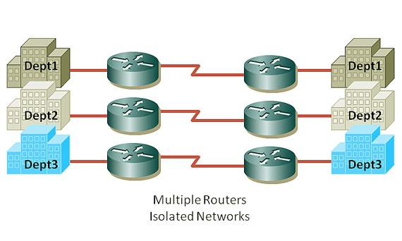
Without VRF

With VRF you can have isolation in a single device – separate routing table for individual interfaces:

VRF-Lite

While the “VRF Lite” equals to “VRF without  the need to run MPLS” in the network,
VRF plays a major role in MPLS networks. So whenever we use VRF without MPLS it’s VRF lite.
But why we need VRF in MPLS networks? Because we want to route customers networks,
they might have overlapped IP addresses. With having multiple VRFs, each customer can have the
same address that other customer might like to use without any problem :

VRF&MPLS

Interfaces in a VRF can be either physical, or logical, such as VLAN SVIs, but a Layer 3 interface
cannot belong to more than one VRF at any time. So the configuration should be easy!
First define each VRF and then allocate desired interface(s) to each VRF.

So let’s lab it up, Here’s our plan :

VRF Lite

We have R2 and R3 connecting 6 networks together, three networks behind R2 and three
network on the right side of the above picture – connected to R3. One each router we create
two VRF, (and there’s always a global routing instance so total of three for each side).
One global routing table and two VRF – VRF23 and VRF32. We have same VRFs on R3.
The requirement is simple, making a connectivity between VRF23 on the right side to the VRF23
on the left side and so on for VRF32.

R2#show ip int br
Interface                  IP-Address      OK?
Ethernet0/0                192.168.0.2     YES
Ethernet0/1                192.168.23.2    YES
Ethernet0/2                192.168.32.2    YES
Ethernet0/3                unassigned      YES
Loopback0                  2.2.2.2         YES
Loopback23                 192.168.123.2   YES
Loopback32                 192.168.132.2   YES

And on R3:

R3#sh ip int br
Interface                  IP-Address      OK?
Ethernet0/0                192.168.0.3     YES
Ethernet0/1                192.168.23.3    YES
Ethernet0/2                192.168.32.3    YES
Ethernet0/3                unassigned      YES
Loopback0                  3.3.3.3         YES
Loopback23                 192.168.223.3   YES
Loopback32                 192.168.232.3   YES

Yes, I have simulated networks with loopback interfaces… If we don’t put interfaces in their
appropriate
VRF, all route will be exposed to all networks. But we don’t want it! we want to keep’em
separated. Fair enough,
let’s go to the configuration part:

R2:
ip vrf 23
rd 1:23

!
ip vrf 32
rd 1:32

!
interface Loopback0
ip address 2.2.2.2 255.255.255.0
!
interface Loopback23
ip vrf forwarding 23
ip address 192.168.123.2 255.255.255.0
!
interface Loopback32
ip vrf forwarding 32
ip address 192.168.132.2 255.255.255.0
!
interface Ethernet0/0
ip address 192.168.0.2 255.255.255.0
!
interface Ethernet0/1
ip vrf forwarding 23
ip address 192.168.23.2 255.255.255.0
!
interface Ethernet0/2
ip vrf forwarding 32
ip address 192.168.32.2 255.255.255.0
!

R3:

ip vrf 23
rd 1:23

!
ip vrf 32
rd 1:32

!
interface Loopback0
ip address 3.3.3.3 255.255.255.0
!
interface Loopback23
ip vrf forwarding 23
ip address 192.168.223.3 255.255.255.0
!
interface Loopback32
ip vrf forwarding 32
ip address 192.168.232.3 255.255.255.0
!
interface Ethernet0/0
ip address 192.168.0.3 255.255.255.0
!
interface Ethernet0/1
ip vrf forwarding 23
ip address 192.168.23.3 255.255.255.0
!
interface Ethernet0/2
ip vrf forwarding 32
ip address 192.168.32.3 255.255.255.0
!

So let’s see what we have done by two simple commands :

R2#sh ip vrf
Name                          Default RD          Interfaces
23                            1:23                Lo23
Et0/1
32                            1:32                Lo32
Et0/2

R2#sh ip route vrf *

2.0.0.0/24 is subnetted, 1 subnets
C       2.2.2.0 is directly connected, Loopback0
C    192.168.0.0/24 is directly connected, Ethernet0/0

Routing Table: 23
C    192.168.123.0/24 is directly connected, Loopback23
C    192.168.23.0/24 is directly connected, Ethernet0/1

Routing Table: 32
C    192.168.132.0/24 is directly connected, Loopback32
C    192.168.32.0/24 is directly connected, Ethernet0/2

Now, we have three different routing tables: global, VRF23 and VRF32 on each router.
The Ethernet interface 0/o of R2 is connected to 0/0 of R3 in the global routing table
(192.168.0.0/24).
Ethernet 0/1 of both devices are connected on another VRF which is 23 and also ethernet0/2 on VRF32.
So these two should be able to ping each other inside each VRF, let’s try it now:

R3#ping 192.168.0.2
!!!!!
Success rate is 100 percent (5/5), round-trip min/avg/max = 10/10/10 ms

R3#ping vrf 23 192.168.23.2
!!!!!
Success rate is 100 percent (5/5), round-trip min/avg/max = 10/10/10 ms

R3#ping vrf 32 192.168.32.2
!!!!!
Success rate is 100 percent (5/5), round-trip min/avg/max = 10/10/10 ms

But it’s not enough, these are connected interfaces on both ends, what about networks behind
each router, they should have a route to the appropriate network on the other side (loopbacks).
We can achieve this requirement just like how we solve it in everyday life, one static route or a using
VRF-aware dynamic routing protocol… let’s start with a static route within one VRF.

R2#conf t
R2(config)#ip route vrf 23 192.168.223.3 255.255.255.255 192.168.23.3
R2(config)#end
R2#sh ip route vrf 23

Routing Table: 23
Gateway of last resort is not set

C    192.168.123.0/24 is directly connected, Loopback23
C    192.168.23.0/24 is directly connected, Ethernet0/1
192.168.223.0/32 is subnetted, 1 subnets
S       192.168.223.3 [1/0] via 192.168.23.3


R2#ping vrf 23 192.168.223.3

Type escape sequence to abort.
Sending 5, 100-byte ICMP Echos to 192.168.223.3, timeout is 2 seconds:
!!!!!
Success rate is 100 percent (5/5), round-trip min/avg/max = 10/10/10 ms

Very good… so lets try to run RIP inside VRF23 between R2 and R3… it should discover networks and
create a
RIP entry in VRF routing table.

VRF-Lite RIP

VRF-Lite-RIP

R2:
router rip
!
address-family ipv4 vrf 23
network 192.168.23.0
network 192.168.123.0
no auto-summary
version 2
exit-address-family
!

R3:
router rip
!
address-family ipv4 vrf 23
network 192.168.23.0
network 192.168.223.0
no auto-summary
version 2
exit-address-family
!

R2#sh ip route vrf 23

Routing Table: 23
Gateway of last resort is not set

C    192.168.123.0/24 is directly connected, Loopback23
C    192.168.23.0/24 is directly connected, Ethernet0/1
R    192.168.223.0/24 [120/1] via 192.168.23.3, 00:00:02, Ethernet0/1

R3#sh ip route vrf 23

Routing Table: 23
Gateway of last resort is not set

R    192.168.123.0/24 [120/1] via 192.168.23.2, 00:00:14, Ethernet0/1
C    192.168.23.0/24 is directly connected, Ethernet0/1
C    192.168.223.0/24 is directly connected, Loopback23

What about EGIRP? Is it VRF-aware? Yes it is…

VRF-Lite EIGRP
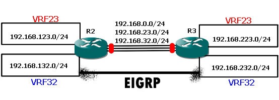
VRF-Lite-EIGRP

R2:

router eigrp 1
auto-summary
!
address-family ipv4 vrf 32
network 192.168.32.0
network 192.168.132.0
no auto-summary
autonomous-system 32
exit-address-family

R2#sh ip eigrp vrf 32 neighbors
IP-EIGRP neighbors for process 32
H   Address           Interface    Hold Uptime   SRTT   RTO  Q  Seq
(sec)         (ms)       Cnt Num
0   192.168.32.3      Et0/2        12   00:12:31  177   1062  0  4


Note: Don’t forget autonomous-system command inside each EIGRP address-family.

VRF-Lite OSPF

Now, it’s time for our popular standard friend – OSPF to come into the picture :

VRF-Lite-OSPF

Here’s the plan: Run one OSPF process per VRF.

R2:

router ospf 23 vrf 23
log-adjacency-changes
network 192.168.0.0 0.0.255.255 area 0
!
router ospf 32 vrf 32
log-adjacency-changes
network 192.168.0.0 0.0.255.255 area 0
!

R3:

router ospf 23 vrf 23
log-adjacency-changes
network 192.168.0.0 0.0.255.255 area 0
!
router ospf 32 vrf 32
log-adjacency-changes
network 192.168.0.0 0.0.255.255 area 0

R3#sh ip ospf neighbor

Neighbor ID    Pri   State     Dead Time   Address        Interface
192.168.132.2    1   FULL/BDR  00:00:38    192.168.32.2   Ethernet0/2
192.168.123.2    1   FULL/BDR  00:00:38    192.168.23.2   Ethernet0/1

R3#sh ip route vrf *
Gateway of last resort is not set

3.0.0.0/24 is subnetted, 1 subnets
C       3.3.3.0 is directly connected, Loopback0
C    192.168.0.0/24 is directly connected, Ethernet0/0

Routing Table: 23
Gateway of last resort is not set

192.168.123.0/32 is subnetted, 1 subnets
O       192.168.123.2 [110/11] via 192.168.23.2, 00:13:53, Ethernet0/1
C    192.168.23.0/24 is directly connected, Ethernet0/1
C    192.168.223.0/24 is directly connected, Loopback23

Routing Table: 32
Gateway of last resort is not set

192.168.132.0/32 is subnetted, 1 subnets
O       192.168.132.2 [110/11] via 192.168.32.2, 00:13:53, Ethernet0/2
C    192.168.232.0/24 is directly connected, Loopback32
C    192.168.32.0/24 is directly connected, Ethernet0/2

VRF-Lite BGP

It’s not MP-BGP (Multi Protocol BGP), it is VRF-aware BGP… each VRF is using its own address family
to communicate with corresponding VRF on the other side:

VRF-Lite-BGP

Let’s see final configuration for BGP:

R2:
ip vrf 23
rd 1:23

!
ip vrf 32
rd 1:32

!
interface Loopback0
ip address 3.3.3.3 255.255.255.0
!
interface Loopback23
ip vrf forwarding 23
ip address 192.168.223.3 255.255.255.0
!
interface Loopback32
ip vrf forwarding 32
ip address 192.168.232.3 255.255.255.0
!
interface Ethernet0/0
ip address 192.168.0.3 255.255.255.0
!
interface Ethernet0/1
ip vrf forwarding 23
ip address 192.168.23.3 255.255.255.0
!
interface Ethernet0/2
ip vrf forwarding 32
ip address 192.168.32.3 255.255.255.0
!
router bgp 1
no synchronization
bgp log-neighbor-changes
no auto-summary
!
address-family ipv4 vrf 32
neighbor 192.168.32.2 remote-as 1
neighbor 192.168.32.2 activate
no synchronization
network 192.168.232.0
exit-address-family
!
address-family ipv4 vrf 23
neighbor 192.168.23.2 remote-as 1
neighbor 192.168.23.2 activate
no synchronization
network 192.168.223.0
exit-address-family
!

R3:

ip vrf 23
rd 1:23

!
ip vrf 32
rd 1:32

!
interface Loopback0
ip address 2.2.2.2 255.255.255.0
!
interface Loopback23
ip vrf forwarding 23
ip address 192.168.123.2 255.255.255.0
!
interface Loopback32
ip vrf forwarding 32
ip address 192.168.132.2 255.255.255.0
!
interface Ethernet0/0
ip address 192.168.0.2 255.255.255.0
!
interface Ethernet0/1
ip vrf forwarding 23
ip address 192.168.23.2 255.255.255.0
!
interface Ethernet0/2
ip vrf forwarding 32
ip address 192.168.32.2 255.255.255.0
!
router bgp 1
no synchronization
bgp log-neighbor-changes
no auto-summary
!
address-family ipv4 vrf 32
neighbor 192.168.32.3 remote-as 1
neighbor 192.168.32.3 activate
no synchronization
network 192.168.132.0
exit-address-family
!
address-family ipv4 vrf 23
neighbor 192.168.23.3 remote-as 1
neighbor 192.168.23.3 activate
no synchronization
network 192.168.123.0
exit-address-family
!

R2#show ip bgp vpnv4 all
BGP table version is 7, local router ID is 2.2.2.2
Origin codes: i – IGP, e – EGP, ? – incomplete

Network          Next Hop            Metric LocPrf Weight Path
Route Distinguisher: 1:23 (default for vrf 23)
*> 192.168.123.0    0.0.0.0                  0         32768 i
*>i192.168.223.0    192.168.23.3             0    100      0 i
Route Distinguisher: 1:32 (default for vrf 32)
*> 192.168.132.0    0.0.0.0                  0         32768 i
*>i192.168.232.0    192.168.32.3             0    100      0 i

Prevent a Route from being Redistributed from OSPF to BGP

Assume you wanted to prevent a route for 10.0.0.0/24 from being redistributed from OSPF to BGP.
One way to accomplish this would be to define an extended ACL matching this prefix and reference
it from the BGP redistribution route map:

router ospf 1
router-id 2.2.2.2
log-adjacency-changes

!
router bgp 65100
no synchronization
bgp router-id 2.2.2.2
bgp log-neighbor-changes
redistribute ospf 1 route-map OSPF->BGP
neighbor 172.16.23.3 remote-as 65100
no auto-summar
y
!
ip access-list extended OSPF_Redist
deny   ip host 10.0.0.0 host 255.255.255.0
permit ip any any

!
route-map OSPF->BGP permit 10
match ip address OSPF_Redist

The above configuration prevents the exact prefix 10.0.0.0/24 from being advertised by denying the
10.0.0.0 network (“source” address) with a mask of 255.255.255.0 (“destination” address).
All other prefixes are allowed by the permit ip any any statement.

This can be accomplished more intuitively by employing a prefix list:

router ospf 1
router-id 2.2.2.2
log-adjacency-changes

!
router bgp 65100
no synchronization
bgp router-id 2.2.2.2
bgp log-neighbor-changes

redistribute ospf 1 route-map OSPF->BGP
neighbor 172.16.23.3 remote-as 65100
no auto-summary

!
ip prefix-list OSPF_Redist seq 5 deny 10.0.0.0/24
ip prefix-list OSPF_Redist seq 10 permit 0.0.0.0/0 le 32

!
route-map OSPF->BGP permit 10
match ip address prefix-list OSPF_Redis

EIGRP Summary

EIGRP is similar to IGRP only in the sense that it uses the same metrics;

Delay
Bandwidth
Reliability
Load

passive-interface default to block all EIGRP adjacencies

no passive-interface default
!
router eigrp 80
passive-interface interface fastethernet 0/1 – no hello send but still advertise network.
passive-interface default – turns on passive-interface globally on all interfaces.
no passive-interface seial 0/1 – turns off passive-interface on these interfaces.
!
summary 172.16.0.0/16 to 172.16.7.255.
int serial 0/1
ip summary-address eigrp 90 172.16.0.0 255.255.248.0

Use specific wildcard mask
router eigrp 80
network 10.1.2.2 0.0.0.0 (host address only)

no auto-summary – Disables Auto Subnet Summarization.

default route pointing to 192.168.1.0/24
router eigrp 80
network 192.168.1.0
exit
ip default-network 192.168.1.0

in show ip route
will see “s* static route.

Unequal load cost balancing.
eigrp by default uses equal load cost balancing a variance of 1 meaning it will load balance
over 1 equal cost link of the same bandwidth.

configuring variance of 2 will load balance across 2 links as bad as the primary.

router eigrp 80
variance 2

you will see in routing-table 2 routes being used over 2 unequal cost bandwidth links

Frame Relay – locally significant
EIGRP Uses 224.0.0.10 mulicast

EIGRP packet delivery is handled using Reliable Transport Protocol (RTP).
EIGRP uses IP protocol number 88.

EIGRP uses the Neighbor Table to list adjacent routers.
Topology Table lists all the learned routes to a destination.
Routing Table contains the best route to a destination, which is known as the Successor.
The Feasible Successor is a backup route to a destination which is kept in the Topology Table.

Broadcast on router by default are denied.
EIGRP came up with “PSEUDO-BROADCASTS” or Manual Neighbors.

int s0/0
ip address 172.16.124.1 255.255.255.248 multipoint
frame-relay map ip 172.16.124.2 102 broadcast
frame-relay map ip 172.16.124.3 103 broadcast
!
show frame-relay map

Multipoint = everyone is on 1 subnet.
Point-to-Point = everyone is on its own subnet.

Advantage is multipoint it saves ip addresses.

Eigrp manual neighbors disables multicast and uses unicast.

router eigrp 25
neighbors 172.16.124.102
neighbors 172.16.124.103

In frame-relay networks :
Split Horizon is disabled on Physical Interfaces
Split Horizon is enabled on Sub-interfaces
!
Enable split horizon on a sub-interface :
This will allow routing updates to leave interface rather than just receive them :

On a multipoint set-up split-horizon will need to be disabled : Spoke and Hub Topology.

int s0/0.1
no ip split-horizon eigrp 25
!

Supports variable length subnet masks (VLSM).
Automatic Route Summarization.
3 Networks Summarization :

HQ
10.1.1.0/24
10.1.2.0/24
10.1.3.0/24
!
EAST
10.2.1.0/24
10.2.2.0/24
10.2.3.0/24
!
WEST
10.3.1.0/24
10.3.2.0/24
10.3.3.0/24
!
Summary Addresses :
in interface mode :

On HQ
ip summary-address eigrp 25 10.1.0.0 255.255.252.0/
!
On EAST
ip summary-address eigrp 25 10.2.0.0 255.255.252.0
!
On WEST
ip summary-address eigrp 25 10.3.0.0 255.255.252.0

Configure HQ router to utilise up to 30% more of the allocated interface bandwidth
than eigrp’s default configuration
.

EIGRP’s default limits of 50% bandwith of the link bandwidth configured .

e.g
interface bandwidth configured :

int s0/0
bandwith 200
!
HQ router has 2 neighbors peering.

ip bandwidth-percent eigrp 25 80
equal 30% more bandwidth given.

Optionally, you can configure the amount of WAN link bandwidth that an
EIGRP router will use with this command:

Router(config-if)# ip bandwidth-percent eigrp XX

Once EIGRP is configured, you can check the status using the show ip route and
show ip eigrp
commands.

!

MD5 authentication can be used to authorise EIGRP packets.
Configure Authentication Keys
!
config t
key chain EIGRP_KEYS
key 1
key-string CISCO1
accept-lifetime 00:00:00 jan 1 2010 00:00:00 feb 1 2010
send-lifetime 00:00:00 jan 1 2010 00:00:00 feb 1 2010
!
key 2
key-string CISCO2
accept-lifetime 00:00:00 jan 28 2010 infinite
send-lifetime 00:00:00 jan 28 2010 infinite
!
Enable Authentication :
!
config t
int s0/1.1
ip authentication mode eigrp 25 md5
ip authentication key-chain eigrp 25 EIRP_KEYS
!
!
Make sure NTP Clock is synchronised on all router for this to work accurately :
!
Troubleshooting :
debug eigrp packet

!

!

By default, EIGRP stub routers advertise information about two types of routes
back to the hub – directly connected networks and summary routes.

To change this default, use the eigrp stub command followed by the types of
routes you want the stub to advertise back to the hub.

The eigrp stub command run by itself simply configures the router as stub.
!

R1(config)#router eigrp 100
R1(config-router)#eigrp stub ?

!
connected Do advertise connected routes
receive-only Set IP-EIGRP as receive only neighbor
static Do advertise static routes
summary Do advertise summary routes

They will then advertise their directly connected networks and summary
routes
back to the hub and will receive only a default route back from the hub.

EIGRP Stub Routers - CCNP ROUTE Exam

If R5 loses a successor and has no feasible successor, it will not send a
DUAL query packet to any of the stub routers, since it knows they are indeed
stub routers and cannot possibly have or acquire a replacement for the lost
successor route.

Logging EIGRP Neighbor State Changes

You want to log EIGRP neighbor state changes.

Solution

To enable the logging of EIGRP neighbor state changes, use the  eigrp log-neighbor-changes
configuration command:

Router1#configure terminal 
Enter configuration commands, one per line.  End with CNTL/Z.
Router1(config)#router eigrp 55
Router1(config-router)#eigrp log-neighbor-changes
Router1(config-router)#exit
Router1(config)#end
Router1#

Another closely related feature is the eigrp log-neighbor-warnings configuration command:

Router1#configure terminal 
Enter configuration commands, one per line.  End with CNTL/Z.
Router1(config)#router eigrp 55
Router1(config-router)#eigrp log-neighbor-warnings 300
Router1(config-router)#exit
Router1(config)#end
Router1#

When a neighbor relationship is lost, you also lose all of the routing entries for that neighbor.
And the effects of this lost routing information are often felt throughout the network. Therefore,
it can be extremely useful to have a good log of neighbor change events for troubleshooting strange
intermittent network problems.
However, this feature also gives you a good way of looking for faults on links that don’t have a way of
telling you about loss of connectivity.
This command is enabled by default.

Troubleshooting EIGRP And Disabling Split Horizon

EIGRP has been correctly configured on each interface, 
but something odd occurs when we check the EIGRP tables - neither of the
spoke routers can see the other spoke router's loopback network.
!
Because EIGRP runs split horizon by default, R1 cannot send a
route advertisement out the same interface the advertisement was
received upon to begin with.
R1 is learning about R2's loopback and R3's loopback on Serial0,
so R1 cannot advertise those routes right back out the same interface.
We've got two choices - we can set up subinterfaces on R1 or we can
disable split horizon on R1's Serial0 interface

Let's disable SH with EIGRP, since the command is a little different than
what you may have seen in your studies.
!
R1(config)#int serial0
R1(config-if)#no ip split-horizon eigrp 100

Passive-Interface

The passive interface feature is used to make a routing protocol accept
routing information from neighbors, but prevent information from being
advertised to neighbors.

EIGRP discovers neighbors using hello messages before accepting routes and
installing them in the routing table. Hello messages are normally sent and
received on an interface configured for EIGRP.

However, the passive interface feature in EIGRP makes an interface stop sending
and receiving hello messages. This tears down any existing neighbor relationships
and stops learning routes from any EIGRP neighbors available on the interface and
configured as passive.

To enable Passive interface globally on all interfaces :
config t
router eigrp 10
passive-interface default 
then you will disable passive-interface on specified neighbor interfaces :


config t
router eigrp 10
no passive-interface loopback 0


To verify rather or not an interface is in passive-mode you can use :  
show ip protocols. 
Best Practices is to enable "Passive-Interface Default" on all interfaces
and to disable run the "no passive-interface fa0/0" on individual interfaces
to allow hello messages to communicate between neighbors to advertise their
networks.

Resolve IP MTU Fragmentation with GRE

This scenario illustrates GRE fragmentation.

Remember that you fragment before encapsulation for GRE, then do PMTUD for the
data packet, and the DF bit is not copied when the IP packet is encapsulated by GRE.
!
In this scenario, the DF bit is not set. The GRE tunnel interface IP MTU is,
by default, 24 bytes less than the physical interface IP MTU,
so the GRE interface IP MTU is 1476.

pmtud_ipfrag_11.gif

  1. The the sender sends a 1500-byte packet (20 byte IP header + 1480 bytes
    of TCP payload)
    .
  2. Since the MTU of the GRE tunnel is 1476, the 1500-byte packet is broken
    into two IP fragments of 1476 and 44 bytes, each in anticipation of the
    additional 24 byes of GRE header
    .
  3. The 24 bytes of GRE header is added to each IP fragment.
    Now the fragments are 1500 (1476 + 24) and 68 (44 + 24) bytes each
    .
  4. The GRE + IP packets containing the two IP fragments are forwarded
    to the GRE tunnel peer router
    .
  5. The GRE tunnel peer router removes the GRE headers from the two packets.
  6. This router forwards the two packets to the destination host.
  7. The destination host reassembles the IP fragments back into the original
    IP datagram
    .


Additional Notes :

Under normal circumstances, when two hosts communicate via TCP,
they communicate with each other to determine the Send Maximum Segment Size (SMSS).
Often this turns out to be 1500 bytes, which not coincidentally, is the maximum amount
of payload in an Ethernet frame
.
All is well until a combination of technologies combine to break the system.

First, the packets travel through a GRE (generic routing encapsulation) tunnel across
an Ethernet interface. This encapsulation tacks on 24 bytes
.

1500 – 24 = 1476

Thus, if either host sends a packet that is larger than 1476, the packet must be
fragmented (typically by one of the tunnel endpoints) to cross the tunnel.
Unfortunately, the hosts do not realize this, because they have only communicated with
one another and agreed upon the 1500 value, but connectivity isn’t broken.

At this point, any one of a number of things can break this connectivity.
If the transmitting host sets the Don’t Fragment bit, the router will be forced to drop
the packet. However, it will *usually* send an ICMP (Internet Control Message Protocol)
message
informing the sender to use smaller packets. But even if it sends the ICMP messages,
they are often filtered or blocked by firewalls somewhere in the path, so the host never knows
why the packet wasn’t delivered.

Another problem that can occur is a firewall that blocks fragmented packets.

Cisco Eigrp Summary 2

Variance

Every routing protocol supports equal cost path load balancing. In addition,
Interior Gateway Routing Protocol (IGRP) and EIGRP also support unequal cost path load balancing.

Use the variance n command in order to instruct the router to include routes with a metric of less
than n times the minimum metric route for that destination.

The variable n can take a value between 1 and 128.
The default is 1, which means equal cost load balancing.
Traffic is also distributed among the links with unequal costs, proportionately,
with respect to
the metric.

router eigrp 1
network x.x.x.x
variance 2
( load balance over 2 unequal cost links).

Traffic Sharing

EIGRP not only provides unequal cost path load balancing, but also intelligent load balancing,
such as traffic sharing.

In order to control how traffic is distributed among routes when there are multiple routes for
the same destination network that have different costs, use the traffic-share balanced command.
With the keyword balanced, the router distributes traffic proportionately to the ratios of the metrics that
are associated with different routes.

This is the default setting:

router eigrp 1
network x.x.x.x
variance 2
traffic-share balanced

When you use the traffic-share command with the keyword min, the traffic is sent only
across the minimum-cost path, even when there are multiple paths in the routing table.

router eigrp 1
network x.x.x.x
variance 3
traffic-share min across-interfaces

Load Balancing in CEF

Cisco Express Forwarding (CEF) is an advanced Layer 3 switching  technology which can be used for
load balancing in routers. By default, CEF uses  per-destination load balancing.

If it is enabled on an interface, per-destination load balancing forwards packets based on the
path to reach the destination. If two or more parallel paths exist for a destination,
CEF takes the same path (single path) and avoids the parallel paths.

This is a result of the default behavior of CEF. CEF takes the single path in cases when load sharing is
done simultaneously on interfaces of different physical types, such as serial and tunnel.

In order to utilize all the parallel paths in CEF and load balance the traffic, you must enable
per-packet load balancing.
When you have different physical interfaces like serial and tunnel. So, on the basis of the
configuration and topology (serial or tunnel), load sharing can fail to work correctly with the
default CEF load balancing mode.

Enable these commands for load sharing on a per-packet basis:

interface serial 0
ip load-sharing per-packet

no passive-interface default

passive-interface default to block all Eigrp adjacencies. Using no passive-interface default
will allow EIGRP communication.

router eigrp 80
passive-interface interface fastethernet 0/1 – no hello send but still advertise network.
passive-interface default – turns on passive-interface globally on all interface.
no passive-interface seial 0/1 – turns off passive-interface on these interfaces.

Ip summary-address eigrp

To configure a summary aggregate address for a specified interface, use the
ip summary-address eigrp command in interface configuration mode.

summary 172.16.0.0/16 to 172.16.7.255

int serial 0/1
ip summary-address eigrp 90 172.16.0.0 255.255.248.0

Configured Eigrp Host Address Only.

router eigrp 80
network 10.1.2.2 0.0.0.0
(host address only).

ip default-network

You can use ip default-network when ip routing is enabled on the Cisco router.
When you configure ip default-network the router considers routes to that network for installation
as the gateway of last resort on the router.

For every network configured with,  if a router has a route to that network, that route is flagged as
a candidate default route.

ip default-network 192.168.1.0

“show ip route” will see s* static route.

ASA – Group Object

Create a Object-Group icmp-type ICMP traffic :

object-group icmp-type INBOUND
description Permit necessary inbound ICMP traffic
icmp-object echo
icmp-object echo-reply
icmp-object unreachable
icmp-object time-exceeded

Create a Object-Group service for TCP traffic :

object-group service INBOUND tcp
description Inbound Access
port-object eq 3389
port-object range 9998 9999

ADSL2 v ADSL2+

There’s a common misconception that ADSL2+ is faster than ADSL2 on any line.
That’s not really the case. In simple terms,

ADSL2+ utilises twice the frequency range available on your phone line that ADSL2 does.
This again, in simple terms means twice as fast BUT that is only seen on short low attenuation lines.

If your line is only capable of supporting 7meg on ADSL2 then it’s only capable of supporting 7meg on ADSL2+
as it can only usually allow the use of the same frequencies for both (see below).

However, if you’re lucky enough to have a line that can support higher frequencies then you get up to :
 
12meg
on ADSL2 (the maximum possible)
but up to
24meg on ADSL2+.

The cross over between ADSL2 and ADSL2+ is therefore in the 10-12 meg range (typically 35-40db if the line is relatively noise free).

It can give faster speeds but usually only on short lines as explained above.
The only time that wouldn’t be true is for a moderately short line
(that offered some higher frequencies above those usable by ADSL2)
that had induced noise at the lower frequencies and was clean at higher frequencies,
in which case ADSL2+ would possibly be better as it could use those higher frequencies.

There is also the possibility that a network uses equipment whose firmware works better in
certain conditions with specific ADSL modes hence why it is mentioned G.DMT sometimes being
better for problem lines.

Cisco: 1841 – 3G Configuration

This configuration example is for use with a 3G WIC card within a Cisco based
Router.

This was configured with a Vodafone Network.

Initialization

Place the SIM card into it, then insert the card in the router and power it on.

Create a Profile specific to your mobile ISP

  • Insert the APN told by your ISP (Vodafone UK: ‘Internet’ username: ‘web’ password: ‘web’)
  • Insert the authentication method (chap or pap) and the credentials, also supplied from your ISP

Below is an example of a Vodafone UK Cellar Profilule.
Router# cellular 0/0/0 gsm profile create 1 Internet chap web web

From the profile you’ve just created, you can review it using command

router# sh cellular 0 profile

Profile Information
====================
Profile 1 = ACTIVE
--------
PDP Type = IPv4
PDP address = 192.168.1.1
Access Point Name (APN) = Internet
Authentication = PAP
Username: web, Password: web 

* - Default profile

Configuration

You need to define a chat script first, which is used for modem setup and call
initialization. If you are familiar with IOS dial configurations, you feel at home.
Please note that the last number in the dial string (1 in the example below) refers
to the modem profile number you hopefully have defined earlier.

! your chat script
chat-script vodafone “” “ATDT*98*1#” TIMEOUT 60 CONNECT

! the bare interface config
! subcommands at the Cellular interface

interface Cellular0/0/0
ip address negotiated
ip virtual-reassembly
encapsulation ppp
dialer in-band
dialer idle-timeout 0
dialer string vodafone
dialer-group 1
async mode interactive
ppp chap hostname web
ppp chap password 0 web
ppp ipcp dns request

!

ip route 0.0.0.0 0.0.0.0 Cellular0
dialer-list 1 protocol ip permit

! this is the async line assigned to the 3G modem
you need to specify your chat script here

line 0/0/0
script dialer vodaphone
no exec
rxspeed 3600000
txspeed 384000

If cellular int does not get an ip address, might need to go into
config t and add this line
even thou we see it above :

line 0/0/0
script dialer vodaphone

!
!

show command:

Just in case you need it for troubleshooting, here are the show commands to use.

  • show cellular 0 network
  • show cellular 0 hardware
  • show cellular 0 connection
  • show cellular 0 radio
  • show cellular 0 profile
  • show cellular 0 security
  • show cellular 0 all Debug commands :
  • debug chat Rather than reloading the router to restart the module, you can
    actually using CLI to reset or reboot the module
    :

    debug chat

    router(config)# service internal
    router(config)# exit
    router# test cellular 0 modem-power-cycle ! for rebooting
    router# test cellular 0 modem-reset ! for resetting

    debug commands :

    debug chat
    debug modem
    debug dialer events
    debug ppp authentication

  • Remember to create the Cellular Profile, after tftp config to router :
    cellular 0/0/0 gsm profile create 1 Internet chap web web
  • This is the bare configuration, you will need to add NAT, firewalls etc etc.

Linux Video Driver Version Command

Video Driver Version Command

dmesg | grep NVIDIA
sudo lspci -vvnn | grep 10de


What I did from the command line is to find the packages for nvidia

(dpkg -l | grep nvidia)
and then
apt-get remove nvidia-173 

(or whatever package you get from the previous command).

The problem is that you will still have the nvidia modues listed in xorg.conf.
So, I also  mv /etc/X11/xorg.conf /etc/X11/xorg.conf_backup
and rebooted.

I landed in a graphical mode as usual, without the nvidia GL stuff,
but then there are graphical tools to set it up.

At this state, it’s safe to delete the xorg.conf backup you just created.

####################
Whenever I try to start my computer from kernel version 3 (it boots fine with 2.6) Kubuntu stops booting

altogether.

11.10 stops booting at “Checking battery state … [OK]”

I had to reinstall my graphics drivers.

sudo apt-get install --reinstall nvidia-173

Home Linux Ubuntu Iptables Firewall Rule

# Generated by iptables-save v1.4.4 on Wed Dec 29 15:11:27 2010
*filter
:INPUT ACCEPT [0:0]
:FORWARD ACCEPT [0:0]
:OUTPUT ACCEPT [0:0]
-A INPUT -i lo -j ACCEPT
-A INPUT -d 127.0.0.0/8 ! -i lo -j REJECT –reject-with icmp-port-unreachable
-A INPUT -m state –state RELATED,ESTABLISHED -j ACCEPT
-A INPUT -d 192.168.2.4/32 -i eth0 -p tcp -m tcp –dport 222 -j ACCEPT
-A INPUT -d 192.168.2.4/32 -i eth0 -p tcp -m tcp –dport 222 -m state –state NEW -m recent –update –seconds 60 –hitcount 8 –rttl –name SSH –rsource -j DROP
-A INPUT -d 172.16.254.3/32 -i eth0 -p tcp -m tcp –dport 8080 -j ACCEPT
-A INPUT -d 10.20.254.254/32 -i eth0 -p tcp -m tcp –dport 1723 -j ACCEPT
-A INPUT -d 172.16.254.3/32 -i eth0 -p udp -m udp –dport 7777 -j ACCEPT
-A INPUT -d 172.16.254.3/32 -i eth0 -p udp -m udp –dport 7778 -j ACCEPT
-A INPUT -d 172.16.254.3/32 -i eth0 -p udp -m udp –dport 7787 -j ACCEPT
-A INPUT -d 192.168.2.4/32 -i eth0 -p tcp -m tcp –dport 5800 -j ACCEPT
-A INPUT -d 192.168.2.4/32 -i eth0 -p tcp -m tcp –dport 5900 -j ACCEPT
-A INPUT -d 192.168.2.4/32 -i eth0 -p tcp -m tcp –dport 5901 -j ACCEPT
-A INPUT -d 192.168.2.4/32 -i eth0 -p tcp -m tcp –dport 5902 -j ACCEPT
-A INPUT -d 192.168.2.4/32 -i eth0 -p tcp -m tcp –dport 5938 -j ACCEPT
-A INPUT -s 10.20.254.249/32 -d 192.168.2.4/32 -i ppp0 -p tcp -m tcp –dport 139 -j ACCEPT
-A INPUT -s 192.168.6.0/29 -d 192.168.2.4/32 -i eth0 -p tcp -m tcp –dport 139 -j ACCEPT
-A INPUT -s 172.16.254.3/32 -d 192.168.2.4/32 -i eth0 -p tcp -m tcp –dport 139 -j ACCEPT
-A INPUT -s 172.16.254.3/32 -d 192.168.2.4/32 -i eth0 -p tcp -m tcp –dport 445 -j ACCEPT
-A INPUT -s 10.0.0.0/24 -d 192.168.2.4/32 -i eth0 -p tcp -m tcp –dport 445 -j ACCEPT
-A INPUT -s 10.0.1.0/24 -d 192.168.2.4/32 -i eth0 -p tcp -m tcp –dport 445 -j ACCEPT
-A INPUT -s 192.168.6.0/29 -d 192.168.2.4/32 -i eth0 -p tcp -m tcp –dport 445 -j ACCEPT
-A INPUT -s 10.20.254.249/32 -d 192.168.2.4/32 -i ppp0 -p tcp -m tcp –dport 445 -j ACCEPT
-A INPUT -s 192.168.3.0/29 -d 192.168.2.4/32 -i eth0 -p tcp -m tcp –dport 445 -j ACCEPT
-A INPUT -s 192.168.4.0/28 -d 192.168.2.4/32 -i eth0 -p tcp -m tcp –dport 445 -j ACCEPT
-A INPUT -s 172.16.0.2/32 -d 192.168.2.4/32 -i eth0 -p tcp -m tcp –dport 445 -j ACCEPT
-A INPUT -d 192.168.2.4/32 -i eth0 -p tcp -m tcp –dport 21 -j ACCEPT
-A INPUT -s 192.168.2.1/32 -d 192.168.2.4/32 -i eth0 -p udp -m udp –dport 514 -j ACCEPT
-A INPUT -s 192.168.2.1/32 -d 192.168.2.4/32 -i eth0 -p udp -m udp –dport 9996 -j ACCEPT
-A INPUT -d 192.168.2.4/32 -i eth0 -p udp -m udp –dport 50518 -j ACCEPT
-A INPUT -d 192.168.2.4/32 -i eth0 -p tcp -m tcp –dport 50518 -j ACCEPT
-A INPUT -d 192.168.2.4/32 -i eth0 -p udp -m udp –dport 6881 -j ACCEPT
-A INPUT -s 192.168.2.1/32 -d 10.20.254.248/29 -i eth0 -p icmp -j ACCEPT
-A INPUT -s 192.168.2.1/32 -d 172.16.254.2/32 -i eth0 -p icmp -j ACCEPT
-A INPUT -s 192.168.2.1/32 -d 172.16.254.3/32 -i eth0 -p icmp -j ACCEPT
-A INPUT -s 192.168.4.0/28 -d 192.168.2.4/32 -i eth0 -p icmp -j ACCEPT
-A INPUT -s 192.168.4.0/28 -d 172.16.254.3/32 -i eth0 -p icmp -j ACCEPT
-A INPUT -s 192.168.6.0/29 -d 192.168.2.4/32 -i eth0 -p icmp -j ACCEPT
-A INPUT -s 172.16.0.2/32 -d 192.168.2.4/32 -i eth0 -p icmp -j ACCEPT
-A INPUT -s 10.20.254.248/29 -d 10.20.254.248/29 -i ppp0 -p icmp -j ACCEPT
-A INPUT -s 10.20.254.249/32 -d 192.168.2.4/32 -i ppp0 -p icmp -j ACCEPT
-A INPUT -m limit –limit 5/min -j LOG –log-prefix “iptables denied: ” –log-level 7
-A INPUT -j DROP
-A OUTPUT -s 192.168.2.4/32 -p tcp -m tcp –dport 80 -j ACCEPT
-A OUTPUT -s 172.16.254.3/32 -p tcp -m tcp –sport 8080 -j ACCEPT
-A OUTPUT -s 192.168.2.4/32 -p tcp -m tcp –dport 443 -j ACCEPT
-A OUTPUT -s 10.20.254.254/32 -p tcp -m tcp –sport 1723 -j ACCEPT
-A OUTPUT -s 172.16.254.3/32 -p udp -m udp –sport 7777 -j ACCEPT
-A OUTPUT -s 172.16.254.3/32 -p udp -m udp –sport 7778 -j ACCEPT
-A OUTPUT -s 172.16.254.3/32 -p udp -m udp –sport 7787 -j ACCEPT
-A OUTPUT -s 10.20.254.254/32 -p gre -j ACCEPT
-A OUTPUT -s 192.168.2.4/32 -p tcp -m tcp –dport 5938 -j ACCEPT
-A OUTPUT -s 192.168.2.4/32 -p tcp -m tcp –dport 5900 -j ACCEPT
-A OUTPUT -s 192.168.2.4/32 -p tcp -m tcp –dport 21 -j ACCEPT
-A OUTPUT -s 192.168.2.4/32 -d 192.168.2.1/32 -p tcp -m tcp –dport 2222 -j ACCEPT
-A OUTPUT -s 192.168.2.4/32 -d 192.168.3.2/32 -p tcp -m tcp –dport 2223 -j ACCEPT
-A OUTPUT -s 192.168.2.4/32 -d 192.168.4.2/32 -p tcp -m tcp –dport 2223 -j ACCEPT
-A OUTPUT -s 192.168.2.4/32 -d 192.168.2.1/32 -p udp -m udp –dport 53 -j ACCEPT
-A OUTPUT -s 192.168.2.4/32 -p tcp -m tcp –dport 30000 -j ACCEPT
-A OUTPUT -s 192.168.2.4/32 -p icmp -j ACCEPT
-A OUTPUT -s 172.16.254.2/32 -d 192.168.2.1/32 -p icmp -j ACCEPT
-A OUTPUT -s 172.16.254.2/32 -d 172.16.254.1/32 -p icmp -j ACCEPT
-A OUTPUT -s 172.16.254.2/32 -d 172.16.254.3/32 -p icmp -j ACCEPT
-A OUTPUT -s 172.16.254.3/32 -d 172.16.254.1/32 -p icmp -j ACCEPT
-A OUTPUT -s 172.16.254.3/32 -d 172.16.254.2/32 -p icmp -j ACCEPT
-A OUTPUT -s 172.16.254.3/32 -d 192.168.2.4/32 -p icmp -j ACCEPT
-A OUTPUT -s 172.16.254.3/32 -d 192.168.4.0/28 -p icmp -j ACCEPT
-A OUTPUT -s 10.20.254.254/32 -d 192.168.2.1/32 -p icmp -j ACCEPT
-A OUTPUT -s 10.20.254.254/32 -d 192.168.2.4/32 -p icmp -j ACCEPT
-A OUTPUT -s 10.20.254.249/32 -d 192.168.2.4/32 -p icmp -j ACCEPT
-A OUTPUT -s 10.20.254.254/32 -d 10.20.254.249/32 -p icmp -j ACCEPT
-A OUTPUT -s 192.168.2.4/32 -p udp -m udp –dport 69 -j ACCEPT
-A OUTPUT -s 192.168.2.4/32 -p tcp -m tcp –dport 23 -j ACCEPT
-A OUTPUT -s 192.168.2.4/32 -p udp -m udp –dport 123 -j ACCEPT
-A OUTPUT -s 192.168.2.4/32 -d 81.103.221.11/32 -p tcp -m tcp –dport 25 -j ACCEPT
-A OUTPUT -s 192.168.2.4/32 -d 192.168.2.1/32 -p udp -m udp –dport 514 -j ACCEPT
-A OUTPUT -s 192.168.2.4/32 -d 192.168.2.1/32 -p udp -m udp –dport 161 -j ACCEPT
-A OUTPUT -s 192.168.2.4/32 -d 192.168.2.1/32 -p udp -m udp –dport 162 -j ACCEPT
-A OUTPUT -s 192.168.2.4/32 -p tcp -m tcp –dport 4070 -j ACCEPT
-A OUTPUT -s 192.168.2.4/32 -d 192.168.5.2/32 -p tcp -m tcp –dport 9100 -j ACCEPT
-A OUTPUT -s 192.168.2.4/32 -d 94.136.40.61/32 -p tcp -m tcp –dport 110 -j ACCEPT
-A OUTPUT -s 192.168.2.4/32 -p tcp -m tcp –dport 1024:65535 -j ACCEPT
-A OUTPUT -m limit –limit 5/min -j LOG –log-prefix “iptables denied: ” –log-level 7
-A OUTPUT -j DROP
COMMIT
# Completed on Wed Dec 29 15:11:27 2010
# Generated by iptables-save v1.4.4 on Wed Dec 29 15:11:27 2010
*nat
:PREROUTING ACCEPT [430:32842]
:POSTROUTING ACCEPT [0:0]
:OUTPUT ACCEPT [2773:170524]
COMMIT
# Completed on Wed Dec 29 15:11:27 2010
# Generated by iptables-save v1.4.4 on Wed Dec 29 15:11:27 2010
*mangle
:PREROUTING ACCEPT [1735576:104189954]
:INPUT ACCEPT [1735512:104181797]
:FORWARD ACCEPT [0:0]
:OUTPUT ACCEPT [2877496:3782379744]
:POSTROUTING ACCEPT [2874912:3782220690]
COMMIT
# Completed on Wed Dec 29 15:11:27 2010